| |
|
|
Home
> FAQ |
| |
|
|
|
|
|
Frequently
Asked Questions |
| |
|
|
|
|
| |
Where is the
optimal location for mounting your room thermostat?
Where should
I place T2 and T3 sensor in F/C and A/C units?
What
are the installation instructions for RS02 Average Room Temperature
for measuring temperature in large rooms?
download
full resistance temperature table >
Regarding
programmable thermostats, what's the difference between US and EU versions
and 5-1-1 vs. 7?
RS-485
connection instructions
Explanation of BACnet Device Instance Number |
|
Where
is the optimal location for mounting your room thermostat? |
 |
| |
Thermostat
location is most important to ensure it provides a reliable, comfortable
home temperature. Observe the following general rules when selecting a
location:
- Locate it about 5 ft. above the floor.
- Install it on a partitioning wall, not on an outside wall.
- Never expose it to direct light from lamps, sun, fireplaces, etc.
- Avoid locations close to doors that lead outside, windows, or adjoining
outside walls.
- Avoid locations close to radiators, warm air registers, or in the
direct path of heat from them.
- Make sure there are no pipes or duct work in that part of the wall
chosen for the thermostat location.
- Never locate it in a room that is warmer or cooler than the rest
of the home, such as kitchen or hallway.
- The living or dining room is normally a good location, provided
there is no cooking range or refrigerator on opposite side of wall.
|
|
|
|
|
|
| |
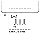
Where
should I place T2 and T3 temperature sensors in a Fan Coil system? |
|
| |
In a Fan Coil system, T2 (Auto-Change-Over sensor)should be placed in
the main pipe before the valve. T3 ("Soft-Start" sensor) should
be placed in the coil itself.
 |
|
|
|
|
|
| |
What are the installation instructions for RS02 Average Room
Temperature for measuring temperature in large rooms? |
|
| |
The
following guidelines refer to Meitav-tec temperature sensor:
Maximum Length with Shield Cable - Wire length for the remote sensor
can be up to 30 meters with standard thermostat cable (not less than
22AWG). If distance is longer than 30 meters, then wire must
be twisted and shielded, 20-22AWG.
Cable must not pass by or be close to any High Voltage Lines or Devices.
At 200 meters, resistance may affect temperature readings by one or
two degrees.
RS02 -
Connection of two remote sensors (in decorative boxes) for average measuring
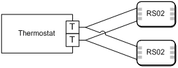
Temperature
~ Resistance Characteristics |
|
| |
| Temp
°C |
7.2 |
10.0 |
12.8
|
15.6 |
18.3 |
21.1 |
23.9 |
26.7 |
29.4 |
32.2 |
| Temp
°F |
45 |
50 |
55 |
60 |
65 |
70 |
75 |
80 |
85 |
90 |
| Res.
K |
115.8 |
100.9 |
88.1 |
77.1 |
67.7 |
59.6 |
52.5 |
46.4 |
41.2 |
36.6 |
download
full resistance temperature table >
|
|
|
|
|
|
|
|
| |
Regarding
programmable thermostats, what's the difference between US and EU versions
and 5-1-1 vs. 7? |
|
| |
Programmable
thermostats can be defined according to two main parameters:
1. Program Type
- USA type, day is typically divided to 2 or 4 periods,
where the user programs different set points
(for Cool & Heat) , without ever turning the system off
- EU type, user can program up to 4 start times, each
with a set point, and 4 stop times per day.
2.
Number of Programs per week
- 5-1-1 signifies a total of 3 different programs per week; 1 for
the weekdays (Monday > Friday),
1 for Saturday and 1 for Sunday
- 7-days signifies 7 programs per week; 1 for each day of the week.
|
|
|
|
|
| |
RS-485
connection instructions |
|
| |
Following
are main points to follow during network installation:
1. Cable Definition
One or more pairs - 120O at 1 Mhz, Made of 24# flexible twisted pairs
overall foil + braid shielded and overall jacketed with a flexible PVC
compound for indoor use.
Examples:
• Westernwire EG202E50 2x2x24# SFTP 120 O Digital Data Cable.
• Teldor 9392002xxx BUS-DOR RS-485/422/232 120O 2x2x24 AWG SF/UTP
cable.
2. Wiring Scheme
Connect all devices by “daisy chain” topology.
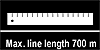
3. Network Limitations
Maximum length of network should be 700 meters
Maximum units per network should be 60 units
Note: longer distance or higher capacity applicable using repeaters
4. Installation Notes
- When pulling the cable, do not use force; this may
stretch the cable and distort its insulation and transmission properties.
- Do not allow the cable to kink, knot, snag, or fray
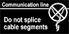
when securing or rolling it out.
- Do not splice cable segments. Use continuous runs
of cable from one device to another.
- Do not cinch cables ties too tightly. Do not crush
cables when securing them with staples or supports. Staple by hand
or use staples with depth stops.
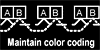
- Maintain the color-coding of all cabling throughout
your system.
- Maintain wire twisting and run the cable jacket
as closely as possible to the termination point.
- Install cables and controllers to minimize the possibility
of accidental contact with other, potentially hazardous and disruptive
power and lighting cables.
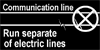
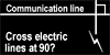
- Do not run communication cables in the same conduit
of electrical cables. If you cross an electrical cable, cross at a
90° angle.
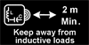
- Do not place communication cables near other bare
power cables, lightning rods, antennas, transformers, steam or hot
water pipes, in any conduit, box, channel, duct or other enclosure
containing power or lighting circuits of any type. Keep communication
cables and controllers at least 2 meters from large inductive loads
(power distribution panels, lighting ballasts, motors, etc.)
5.
Addressing
Use the attached
MAC Address table to define the network addresses of the devices.
6. Termination
First and last devices
in the communication line should be terminated with a 120O resistor
to prevent signal reflection. When applicable, use the “End of
Line” jumpers for this purpose.
7.
Grounding
- Connect
one end of the shield (at the end of the communication line) to a
tested ground (earth). Leave the other end of shield not connected
(on the air).
- Connect
the shields between the devices externally (not through any terminal
of the device).
- Do
not connect the shields to the “ground” or “0”
terminals of the devices.
|
|
| |
8.
MAC Address table |
|
| Addr. |
Switch position |
Addr. |
Switch position |
Addr. |
Switch position |
Addr. |
Switch position |
| 0 |
NOT IN USE |
64 |
7 |
128 |
8 |
192 |
7+8 |
| 1 |
1 |
65 |
1+7 |
129 |
1+8 |
193 |
1+7+8 |
| 2 |
2 |
66 |
2+7 |
130 |
2+8 |
194 |
2+7+8 |
| 3 |
1+2 |
67 |
1+2+7 |
131 |
1+2+8 |
195 |
1+2+7+8 |
| 4 |
3 |
68 |
3+7 |
132 |
3+8 |
196 |
3+7+8 |
| 5 |
1+3 |
69 |
1+3+7 |
133 |
1+3+8 |
197 |
1+3+7+8 |
| 6 |
2+3 |
70 |
2+3+7 |
134 |
2+3+8 |
198 |
2+3+7+8 |
| 7 |
1+2+3 |
71 |
1+2+3+7 |
135 |
1+2+3+8 |
199 |
1+2+3+7+8 |
| 8 |
4 |
72 |
4+7 |
136 |
4+8 |
200 |
4+7+8 |
| 9 |
1+4 |
73 |
1+4+7 |
137 |
1+4+8 |
201 |
1+4+7+8 |
| 10 |
2+4 |
74 |
2+4+7 |
138 |
2+4+8 |
202 |
2+4+7+8 |
| 11 |
1+2+4 |
75 |
1+2+4+7 |
139 |
1+2+4+8 |
203 |
1+2+4+7+8 |
| 12 |
3+4 |
76 |
3+4+7 |
140 |
3+4+8 |
204 |
3+4+7+8 |
| 13 |
1+3+4 |
77 |
1+3+4+7 |
141 |
1+3+4+8 |
205 |
1+3+4+7+8 |
| 14 |
2+3+4 |
78 |
2+3+4+7 |
142 |
2+3+4+8 |
206 |
2+3+4+7+8 |
| 15 |
1+2+3+4 |
79 |
1+2+3+4+7 |
143 |
1+2+3+4+8 |
207 |
1+2+3+4+7+8 |
| 16 |
5 |
80 |
5+7 |
144 |
5+8 |
208 |
5+7+8 |
| 17 |
1+5 |
81 |
1+5+7 |
145 |
1+5+8 |
209 |
1+5+7+8 |
| 18 |
2+5 |
82 |
2+5+7 |
146 |
2+5+8 |
210 |
2+5+7+8 |
| 19 |
1+2+5 |
83 |
1+2+5+7 |
147 |
1+2+5+8 |
211 |
1+2+5+7+8 |
| 20 |
3+5 |
84 |
3+5+7 |
148 |
3+5+8 |
212 |
3+5+7+8 |
| 21 |
1+3+5 |
85 |
1+3+5+7 |
149 |
1+3+5+8 |
213 |
1+3+5+7+8 |
| 22 |
2+3+5 |
86 |
2+3+5+7 |
150 |
2+3+5+8 |
214 |
2+3+5+7+8 |
| 23 |
1+2+3+5 |
87 |
1+2+3+5+7 |
151 |
1+2+3+5+8 |
215 |
1+2+3+5+7+8 |
| 24 |
4+5 |
88 |
4+5+7 |
152 |
4+5+8 |
216 |
4+5+7+8 |
| 25 |
1+4+5 |
89 |
1+4+5+7 |
153 |
1+4+5+8 |
217 |
1+4+5+7+8 |
| 26 |
2+4+5 |
90 |
2+4+5+7 |
154 |
2+4+5+8 |
218 |
2+4+5+7+8 |
| 27 |
1+2+4+5 |
91 |
1+2+4+5+7 |
155 |
1+2+4+5+8 |
219 |
1+2+4+5+7+8 |
| 28 |
3+4+5 |
92 |
3+4+5+7 |
156 |
3+4+5+8 |
220 |
3+4+5+7+8 |
| 29 |
1+3+4+5 |
93 |
1+3+4+5+7 |
157 |
1+3+4+5+8 |
221 |
1+3+4+5+7+8 |
| 30 |
2+3+4+5 |
94 |
2+3+4+5+7 |
158 |
2+3+4+5+8 |
222 |
2+3+4+5+7+8 |
| 31 |
1+2+3+4+5 |
95 |
1+2+3+4+5+7 |
159 |
1+2+3+4+5+8 |
223 |
1+2+3+4+5+7+8 |
| 32 |
6 |
96 |
6+7 |
160 |
6+8 |
224 |
6+7+8 |
| 33 |
1+6 |
97 |
1+6+7 |
161 |
1+6+8 |
225 |
1+6+7+8 |
| 34 |
2+6 |
98 |
2+6+7 |
162 |
2+6+8 |
226 |
2+6+7+8 |
| 35 |
1+2+6 |
99 |
1+2+6+7 |
163 |
1+2+6+8 |
227 |
1+2+6+7+8 |
| 36 |
3+6 |
100 |
3+6+7 |
164 |
3+6+8 |
228 |
3+6+7+8 |
| 37 |
1+3+6 |
101 |
1+3+6+7 |
165 |
1+3+6+8 |
229 |
1+3+6+7+8 |
| 38 |
2+3+6 |
102 |
2+3+6+7 |
166 |
2+3+6+8 |
230 |
2+3+6+7+8 |
| 39 |
1+2+3+6 |
103 |
1+2+3+6+7 |
167 |
1+2+3+6+8 |
231 |
1+2+3+6+7+8 |
| 40 |
4+6 |
104 |
4+6+7 |
168 |
4+6+8 |
232 |
4+6+7+8 |
| 41 |
1+4+6 |
105 |
1+4+6+7 |
169 |
1+4+6+8 |
233 |
1+4+6+7+8 |
| 42 |
2+4+6 |
106 |
2+4+6+7 |
170 |
2+4+6+8 |
234 |
2+4+6+7+8 |
| 43 |
1+2+4+6 |
107 |
1+2+4+6+7 |
171 |
1+2+4+6+8 |
235 |
1+2+4+6+7+8 |
| 44 |
3+4+6 |
108 |
3+4+6+7 |
172 |
3+4+6+8 |
236 |
3+4+6+7+8 |
| 45 |
1+3+4+6 |
109 |
1+3+4+6+7 |
173 |
1+3+4+6+8 |
237 |
1+3+4+6+7+8 |
| 46 |
2+3+4+6 |
110 |
2+3+4+6+7 |
174 |
2+3+4+6+8 |
238 |
2+3+4+6+7+8 |
| 47 |
1+2+3+4+6 |
111 |
1+2+3+4+6+7 |
175 |
1+2+3+4+6+8 |
239 |
1+2+3+4+6+7+8 |
| 48 |
5+6 |
112 |
5+6+7 |
176 |
5+6+8 |
240 |
5+6+7+8 |
| 49 |
1+5+6 |
113 |
1+5+6+7 |
177 |
1+5+6+8 |
241 |
1+5+6+7+8 |
| 50 |
2+5+6 |
114 |
2+5+6+7 |
178 |
2+5+6+8 |
242 |
2+5+6+7+8 |
| 51 |
1+2+5+6 |
115 |
1+2+5+6+7 |
179 |
1+2+5+6+8 |
243 |
1+2+5+6+7+8 |
| 52 |
3+5+6 |
116 |
3+5+6+7 |
180 |
3+5+6+8 |
244 |
3+5+6+7+8 |
| 53 |
1+3+5+6 |
117 |
1+3+5+6+7 |
181 |
1+3+5+6+8 |
245 |
1+3+5+6+7+8 |
| 54 |
2+3+5+6 |
118 |
2+3+5+6+7 |
182 |
2+3+5+6+8 |
246 |
2+3+5+6+7+8 |
| 55 |
1+2+3+5+6 |
119 |
1+2+3+5+6+7 |
183 |
1+2+3+5+6+8 |
247 |
1+2+3+5+6+7+8 |
| 56 |
4+5+6 |
120 |
4+5+6+7 |
184 |
4+5+6+8 |
248 |
4+5+6+7+8 |
| 57 |
1+4+5+6 |
121 |
1+4+5+6+7 |
185 |
1+4+5+6+8 |
249 |
1+4+5+6+7+8 |
| 58 |
2+4+5+6 |
122 |
2+4+5+6+7 |
186 |
2+4+5+6+8 |
250 |
2+4+5+6+7+8 |
| 59 |
1+2+4+5+6 |
123 |
1+2+4+5+6+7 |
187 |
1+2+4+5+6+8 |
251 |
1+2+4+5+6+7+8 |
| 60 |
3+4+5+6 |
124 |
3+4+5+6+7 |
188 |
3+4+5+6+8 |
252 |
3+4+5+6+7+8 |
| 61 |
1+3+4+5+6 |
125 |
1+3+4+5+6+7 |
189 |
1+3+4+5+6+8 |
253 |
1+3+4+5+6+7+8 |
| 62 |
2+3+4+5+6 |
126 |
2+3+4+5+6+7 |
190 |
2+3+4+5+6+8 |
254 |
2+3+4+5+6+7+8 |
| 63 |
1+2+3+4+5+6 |
127 |
1+2+3+4+5+6+7 |
191 |
1+2+3+4+5+6+8 |
255 |
1+2+3+4+5+6+7+8 |
|
| |
|
|
| |
|
|
|
|
|
|
|
|
| |
Explanation of BACnet Device Instance Number |
|
| |
BACnet thermostats object list contains the Analog Value "BacnetDeviceInstanceNumber"
"Read/Write"; range 1...4194303; default value 315000 + MAC.
This Analog Value is the representation of BACnet Device object property “Object identifier”.
It may be changed via BACnet network, and BACnet router must apply it.
After updating the Device Instance Numer, the thermostat may be lost by router,
and it is necessary to rescan network to pick up the thermostat again.
Important notes:
Thermostats in the same loop shall have different Device Instance Numbers.
Two thermostats in different loops may have the same Device Instance Number.
Thermostats in the same loop shall have different MAC addresses!
The default value of the Device Instance Number can be recovered by "Restore default" operation.
|
|